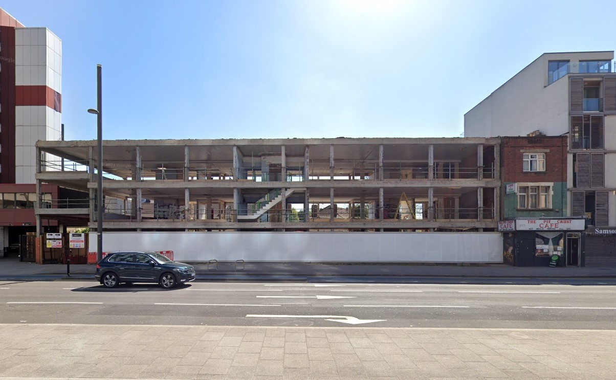
The Mary Ward Settlement – a century old charity – offers adult education, legal advice, and community services. Operating from a Grade II listed building in Queen Square, London, they required larger premises due to their expanding services. They identified Queensway House, now Mary Ward Centre – a derelict 1970s concrete framed building in Stratford – as a potential new home.
Mary Ward obtained a loan from the ‘Skills for Londoners Capital Fund’ to renovate Queensway House. Environmental considerations were crucial, requiring the reuse of the existing frame for funding approval. The space needed to accommodate a Legal Centre, multi-functioning arts theatre, café, teaching areas, and community use. Queensway House was approximately 60% too small, necessitating extension and refurbishment.
Perceived as riskier than a demolition and new build, heavy structural modifications require thorough investigation to understand cost and complexity of retention, incurring significant upfront investment.
A previous engineering assessment identified key risk areas: low concrete strength to the frame (25 N/mm); frame unsuitable to support a dance studio with high imposed/dynamic loading at second floor; ambitious cantilever staircase supported from the core; foundation strengthening throughout due to compressible silt below existing foundations; demolition of the roof slab to support the additional loading as a new floor. The risk level for the client to move forward was too high.
Based on our successful collaboration with the Quantity Surveyor on a similarly complex project, the client was advised to discuss a more detailed approach with us. Initial analysis convinced us that transforming the building from four to six-storeys and full refurbishment could be viable, subject to further investigations and amendments to the design.

Image: AWW

Image: AWW
The building was designed for offices and occupied a split-level site; the front portion three storeys high, and the rear four.
The typical 1970s reinforced concrete (RC) structure has a 220mm to 255mm deep beam and pot slab cast into supporting perimeter and internal beams. Mass concrete pads support the columns, with ground bearing slabs at ground and lower ground floor levels and a retaining wall along the centre of the building, forming the steps in level to the rear. A blockwork central lift and stair core had been previously retrofitted, with two original corner stair cores constructed in brickwork.
Using our prior experience and information available, we identified as many risks as possible and used a thorough methodical approach to reduce them to a level acceptable for the client to proceed with investing in further intrusive and design work. The design team restructured and we were appointed as structural and civil engineers.
We subsequently reviewed building control and planning archives, but found limited original information and few architectural drawings. We formed an assumption about the construction and foundation arrangements using this basic information to inform a series of material tests and opening works to validate the building fabric capabilities and address key risk areas.
Concrete samples and break outs were undertaken on columns, slabs, downstand beams, and walls. A Ferroscan Survey scanned RC elements and local breakouts confirmed bar diameter, spacing, and condition. Reinforcing steel samples were extracted for tensile testing. Given the low sample strength found previously, further concrete samples were taken for compressive strength and carbonation testing.
The testing results of the compressive strength were variable and ranged from C20/25 for beams, C30/37 for columns, and C25/30 for slabs based on mean test values. Carbonation of the concrete was found only at surface level. Capacity of existing beams and columns could be calculated from the results of the investigations and dimensional surveys. A column load design check was performed to adhere to CP 114 and current EC2 in practice.

Image: Richard Chivers
Investigations showed the existing roof RC ribbed slab was insufficient in bending to support the proposed floor build-ups and imposed load.
Other floors used a load comparison of proposed vs existing to justify the educational use, complimented by checks on the ribbed beams. The ground, first, and second floors did not require strengthening.
Several columns along the rear elevation were found to have inadequate biaxial bending capacity from the additional load and required strengthening. The front and central row of columns were sufficient to support the extra storeys.
A 10% load increase on foundations is typically acceptable without significant exploration, but on this project some could experience over 35% increase due to additional loads. Due to the split level basement, underpinning or extending pad foundations would have proved difficult and expensive. Foundations on party wall lines would have also proved complex to strengthen. Boreholes and trial pits revealed some foundation pads were founded within a thin layer of very weak Langley Silt Member, with others in Kempton Park Gravel Member. Lambeth Group Clays were found 5-10.0m below ground level. Analysis was undertaken assuming the foundations were underlain by a thin layer of weak cohesive soil over a cohesive soil of varying stiffness. It was repeated with the same weak cohesive soil over granular soil. Results concluded the ultimate bearing capacity of the soil was highly influenced by changes in the soil mass, and not primarily determined by the thin clay layer underlying the foundation. Only two existing foundations required strengthening. New foundations designed to bear into Kempton Park Gravels with the same settlement criteria.
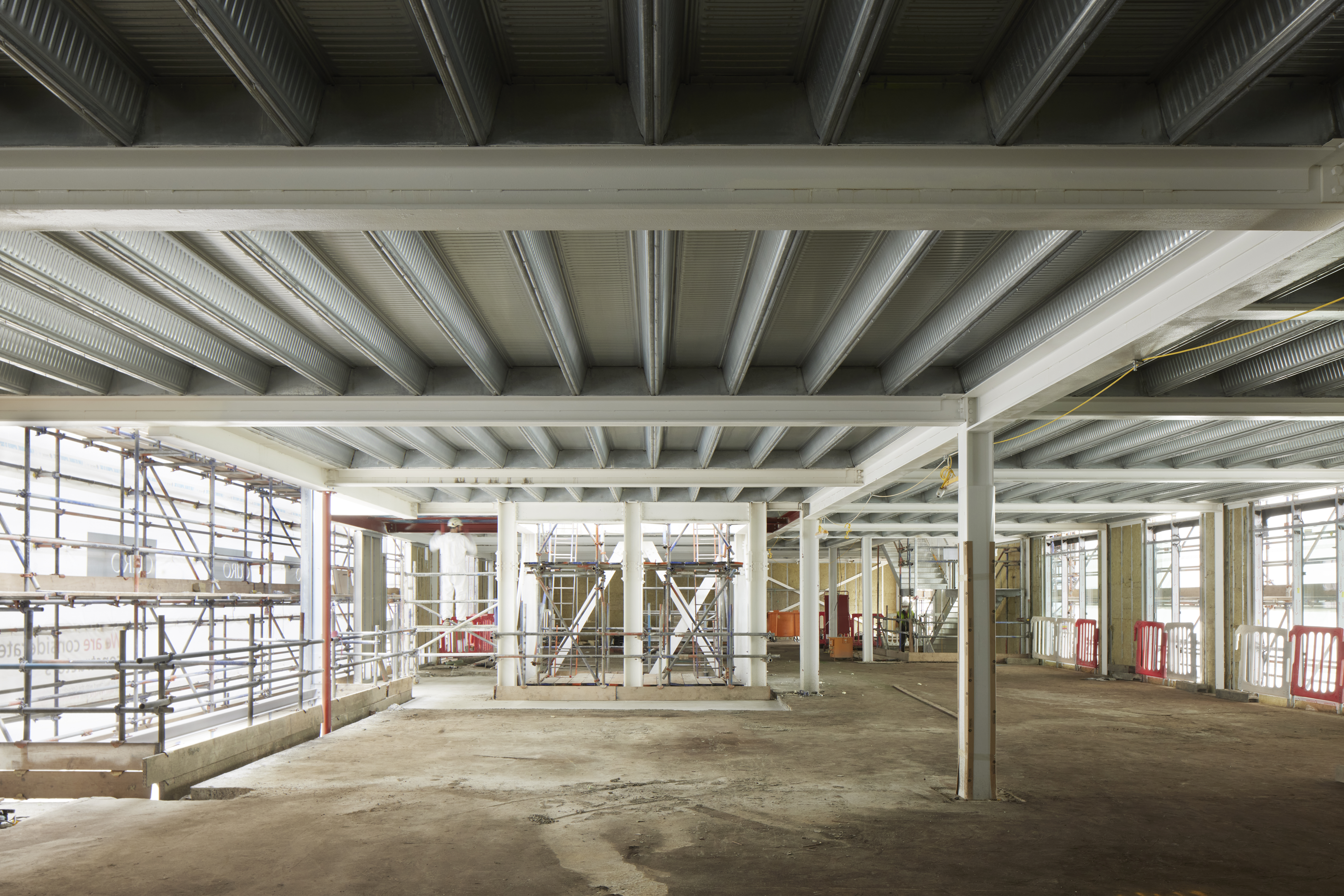
Additional storeys are constructed using steel framing and concrete slab on metal deck. New steelwork strengthens the existing slabs and columns, left exposed to highlight the interface between new and existing and structural modifications. An exposed structure suited the budget and low carbon design goals.

Image: Daniel Shearing
An acoustic floating floor solution was the most economical approach for the dance studio, omitting vibration concerns associated with this space.
Cables were introduced to suspend the staircase landings from the new roof. This largely retained the Architect and client vision while significantly reducing forces onto the structure and reducing complexity and cost. The stairs were reconfigured further to provide additional usable space.
A steel grillage below the third floor acts as a transfer from the new storeys above to the existing frame. Columns were strengthened with PFC sections bolted either side and packed tight to the floor and soffit to take the additional loading.
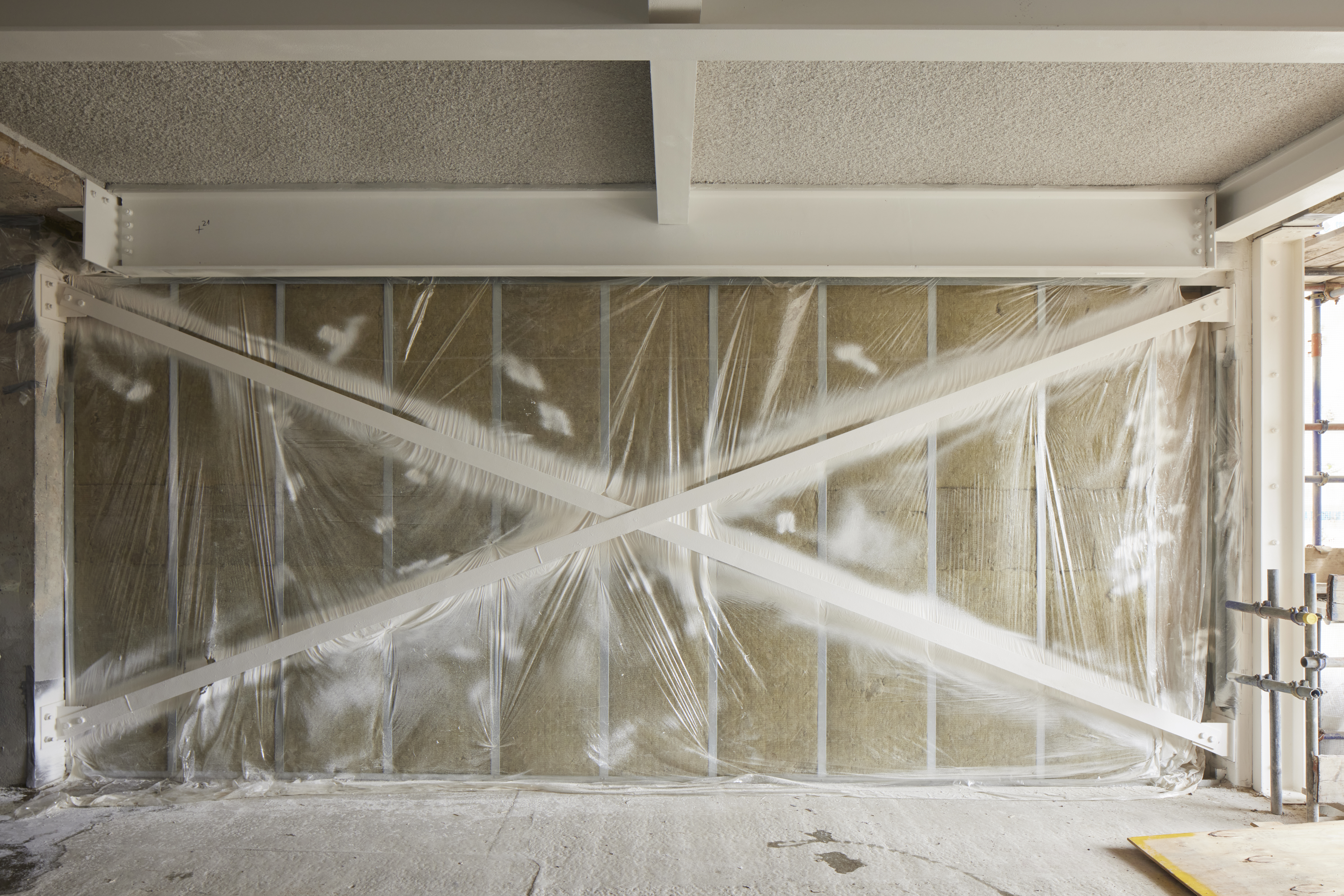
To enhance stability required for the increased wind load from the new taller structure, a new braced lift core, and steel cross bracing at either end of the building were installed, working with existing concrete columns and beams. Investigations confirmed the existing elements, including reinforcement in the columns through to the foundation, had capacity for the additional shear and axial loads and could withstand the design forces without further strengthening. An iterative sensitivity analysis was conducted between the stiffness of new end elevation cross bracing and the braced core stiffness to avoid positional issues of uplift from overturning.

Image: Richard Chivers
The new central lift core needed tension piles to stabilise the taller part of the build and resist overturning forces. The settlement criteria of the piles did not vary greatly between that of the new and existing foundations. When modelling the lift core, small horizontal deflections were anticipated at ground floor given the split level basement. The core is restrained by the existing ground bearing slab and unwanted cracking and force distribution is induced to the existing retaining wall. The base of the steel frame is encased in concrete shear walls, tied to the columns and the piled raft, adding enhanced stiffness at this lower level.
Fire performance cover to the existing reinforced rib beams varied between 8mm – 35mm, therefore failing current code requirements. Finite Element fire analysis was considered for the floor plate but due to low cover in some areas, cementitious spray was applied to the underside of the slabs.
There are no tie beams between the perimeter columns and the internal columns. The columns are tied by the beam and pot floor and investigations and calculations confirmed the designed detailing satisfied the tie force specified in disproportionate collapse code for a Class 2b structure. This approach omitted the need for new tie members which would have added cost, carbon, and service distribution complexity.

Image: Richard Chivers

Image: Daniel Shearing
With the construction sector responsible for 40% of global greenhouse emissions, structural engineers can make a significant impact by reducing embodied carbon associated with designs.
To calculate the CO2 saving by opting for refurbishment, a new steel framed building with concrete slabs on metal decking was created as a comparison; modelled in Revit, assuming same foundations as the refurbishment option.
By fully modelling the frame in Revit, Technicians used the EOC ECO2 plug-in to calculate the volume of new material and the Structural Carbon Tool for CO2 amounts for individual elements. The refurbishment option demonstrated a 40% reduction in embodied carbon when compared to constructing a new building, excluding demolition of the frame, with the refurbishment and extension meeting LETI’s targets.
We implemented a rigorous process of investigation, calculation, and verification to ensure we designed an efficient building and avoid the use of unnecessary materials. Working with the existing structure we aimed to minimise interventions, collaborating closely with the design team to utilise the building’s capacity where possible. This involved numerous design iterations and close collaboration. For the new floors, we explored alternative materials and decided on a deep deck concrete slab spanning between efficient steel beams as the most economical solution with regards to carbon and acoustic requirements. To minimise concrete use further, we specified local concrete mixes with low strength and high GGBS content as strength was not the deciding factor in this case.


Image: SD Engineers
Repurposing the 1970s building posed significant challenges in both design and construction phases. Collaboration was crucial for success, with an enthusiastic client and engaged design/construction team working to mitigate risks and address challenges. Thorough exploration works were instrumental in achieving this level of coordination and problem-solving.
The project heavily relied on the Skills for Capital Londoners Fund for its realisation. Extensive investigative works, crucial for confirming the refurbishment viability, required significant upfront investment – a cost that can be hard to justify for many clients, particularly charities. While VAT is still charged on refurbishment projects, a loan such as this could enable a number of reuse possibilities.
